Overview
The inverted pendulum is a classic control theory problem: a pendulum is mounted upside down on a cart, and the cart must be moved to keep the pendulum balanced vertically. It's an unstable system, meaning without active correction it will simply fall.
I decided to initially pursue this topic as an independent final project in MATH 2406H. The goal of this initial project was to simulate the system and create my own optimization program to find the correct gains for the simulated PID controller. To do this I ultimately derived the equations of motion for the pendulum and simulated it in MATLAB.
This initial project, which included in-depth analysis of the system, laid the groundwork for the physical project depicted here.
Approach
To control the pendulum I used a PD controller. I originally intended to use a feedforward state-space model, like in the initial simulations, but chose the PD controller for simplicity.
- Milestone 1: Built the Physical Rig
- Milestone 2: Developed the Motor Control Algorithm
- Milestone 3: Implemented and Tuned the Controller
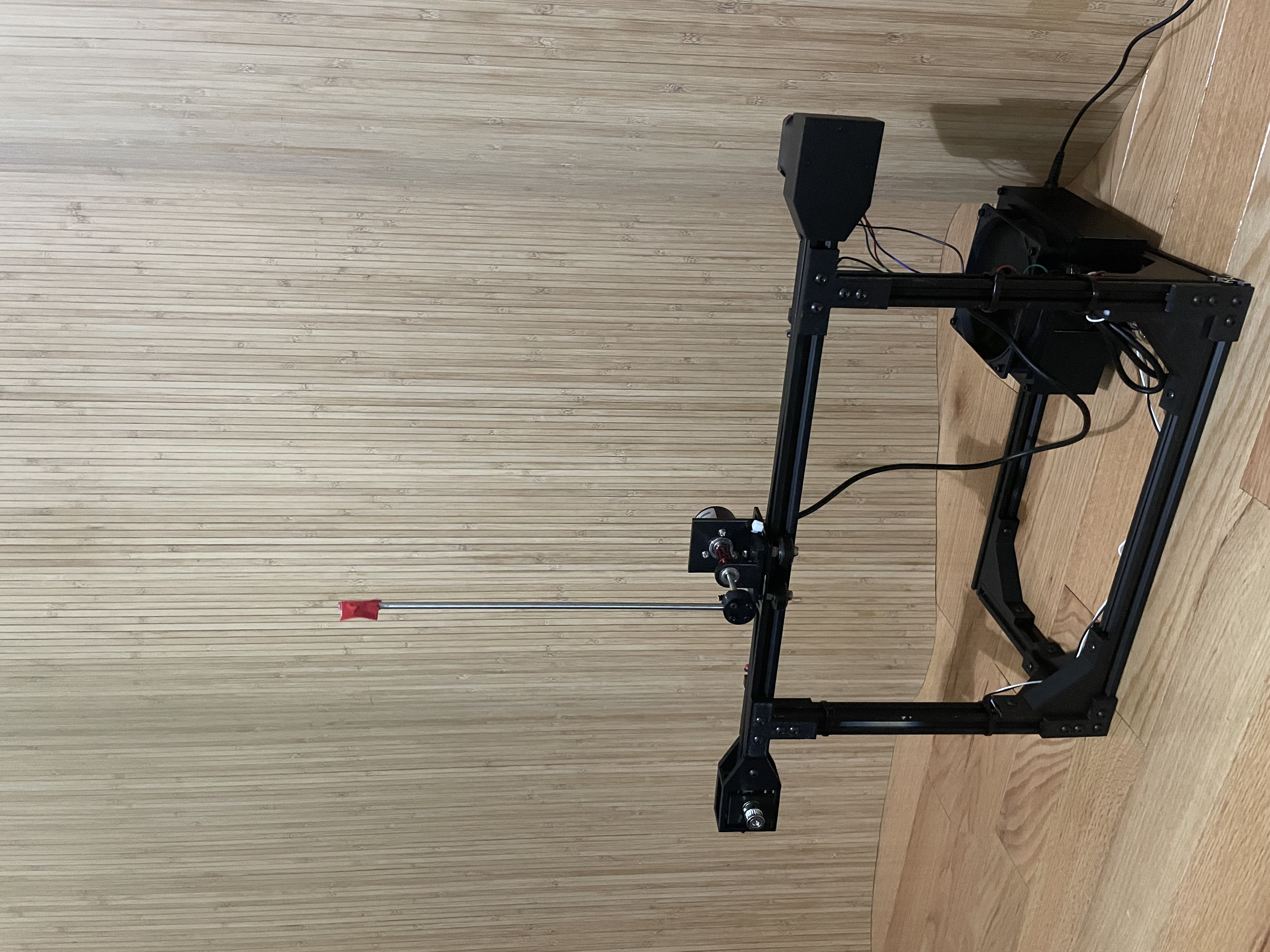
The rig is comprised of 2020 V-slot aluminum extrusion for the main rail where the gantry rides, as well as the legs. I chose this because it offers extensive flexibility while also providing rigidity and a built-in track for the gantry.
The gantry is moved via a belt connected to the stepper motor and the gantry itself. The stepper motor I chose for this project is a standard NEMA 17 stepper capable of 2.1A (part number: 17hs24-2104s) that I was able to scavenge. I chose this stepper because it ensured torque would not be a limiting factor.
Finally, the pendulum mount itself includes an optical encoder (this one). I chose an optical encoder because it is very precise and adds very little friction to the pendulum, allowing the movement to be as smooth as possible.
To control the stepper motor I originally intended to use a simple quadruple half-H bridge driver; however, due to the high current draw of the motor it experienced overheating issues. To fix this I upgraded to a DRV8825 stepper motor driver capable of supplying the full 2.1A.
Developing a control algorithm for the motor to work with the PD controller took a substantial amount of time because of two main reasons: the force applied to the gantry is what matters, and the stepper motor takes time to reach a specified speed without skipping steps.
To remedy the issue of not being able to easily apply a specified force to the gantry I focused on controlling the acceleration, which is easier to calculate using the step information from the stepper motor.
Since the acceleration of the gantry is tracked by the step information from the motor, preventing the stepper motor from skipping steps was imperative. To achieve this I eventually settled on using the AccelStepper library and a combination of hard-coded limits to keep things as simple and reliable as possible.
Once the motor control was taken care of, implementing the PD controller was straightforward. The simulations from my earlier research helped substantially in the tuning process by indicating the relative size of each gain. However, because I ultimately changed approaches and the simulation lacked some variables, it was not entirely accurate.
Challenges
I originally chose a stepper motor for this project because I mistakenly thought the position of the gantry would be important. The pendulum is balanced only by calculating the force to be applied to the gantry, so it is not required to track the position. I discovered this while working on the earlier paper, but decided to use what I had on hand.
This made it harder to program the controller, but it did allow the gantry to stay in the middle of the track with no additional hardware, such as another encoder for the belt. Ultimately, while this decision proved helpful in reducing the total number of components and greatly expanding my knowledge of stepper motor control, a standard motor would be better suited for this project.
Results
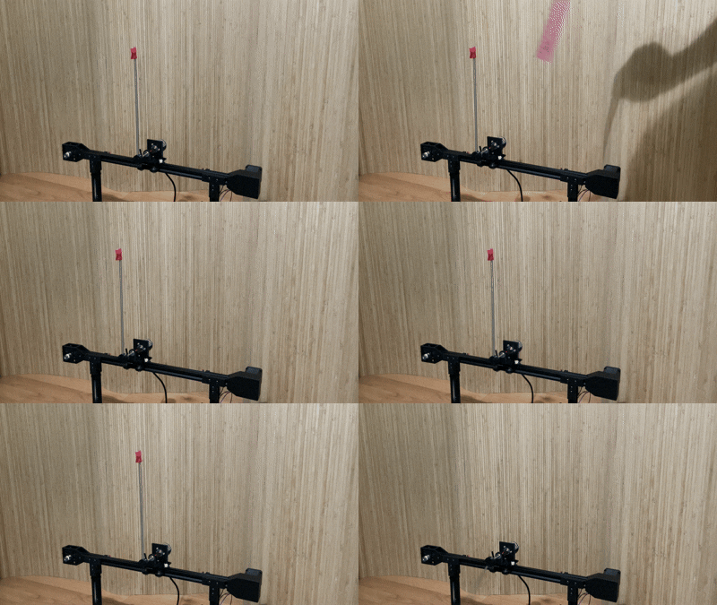
The pendulum is very stable and can balance indefinitely. It can correct disturbances in less than 5 seconds.